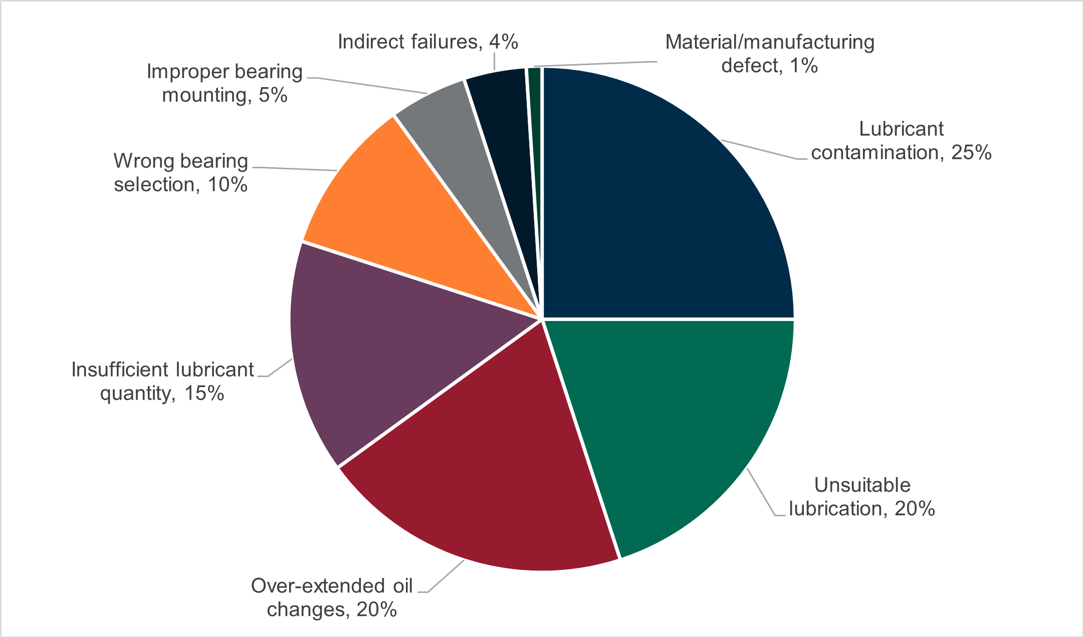
While there are many reasons why centrifugal pumps fail, a high percentage can be attributed to bearing failure caused by lubrication issues. In fact, according to a leading bearing manufacturer, lubrication accounts for up to 80% of all bearing failures (top image). Key factors that induce tribological failures include contamination, insufficient lubricant, improper lubricant, and excessively long relubrication intervals, all of which are preventable. Pump life could be extended by 30-50% by focusing on these four factors.
1. Proper lubrication
Proper lubrication is more than selecting the right oil or grease for the application. Lubrication refers to how the lubricant is kept in a clean and healthy condition in the pump.
Users cannot simply fill a pump full of oil and expect reliability – they must constantly monitor lubricant health, oil level and contamination to avoid unnecessary breakdowns.
One way to do this is through oil analysis. However, for many smaller pumps, the size of the oil pan coupled with an inability to extract a representative oil sample often means that the oil in many pumps remains unmonitored. To overcome this limitation, it is recommended to implement daily or weekly visual inspections, performed by operators, lubrication technicians or mechanics. To be effective, the inspection must include visual clues to help determine the health, cleanliness, and overall oil level in the pump. Inspection checklists should be developed that ask simple questions with binary answers such as:
- Is the oil clean and clear?
- Is the oil level halfway up the sight glass?
Done correctly, visual inspections can detect 80% to 90% of all lubrication problems before they become catastrophic and should be mandatory whenever operator rounds are used.
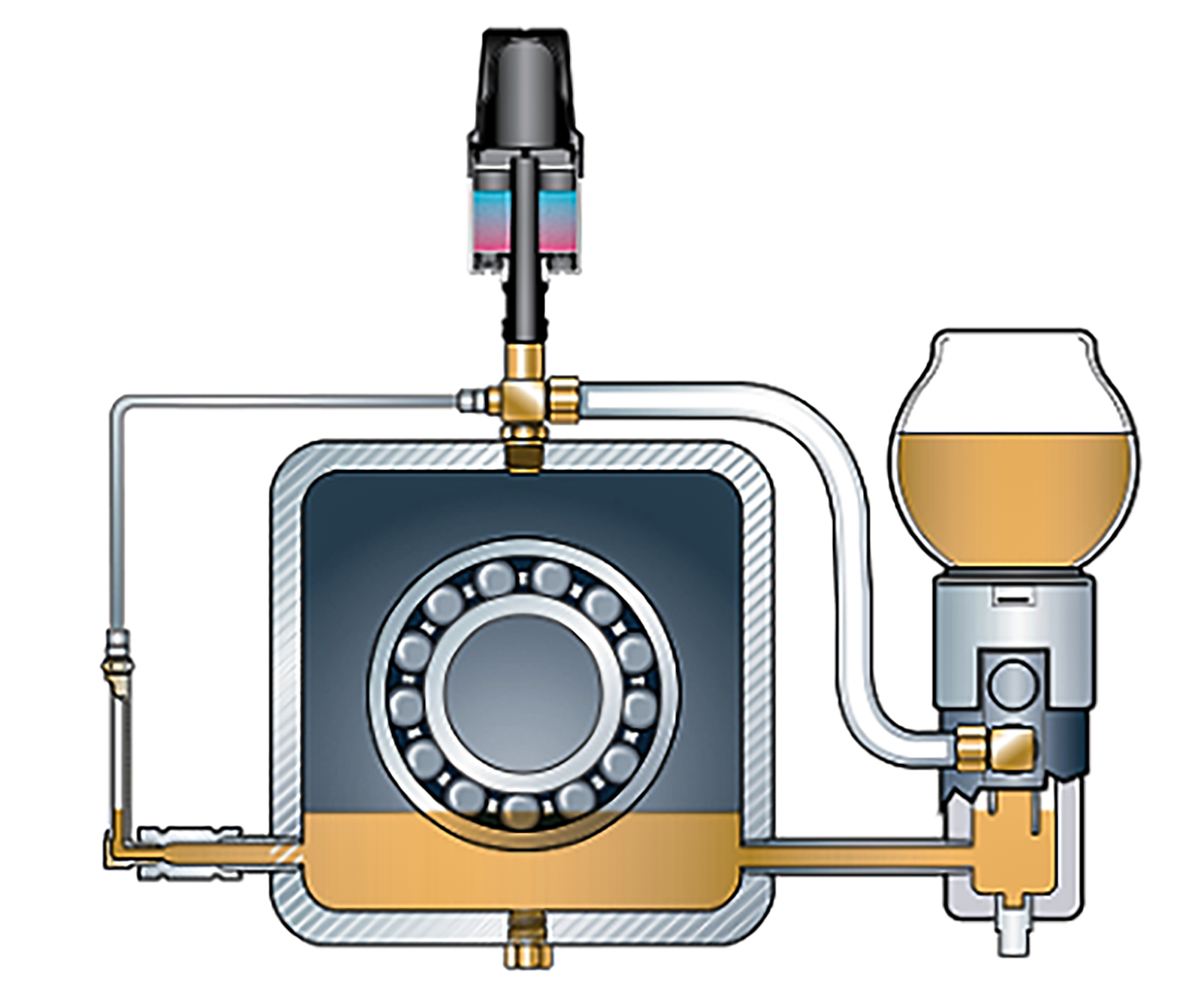
Unfortunately, many process pumps are not set up for visual inspections and must be modified to include simple hardware to detect major lubrication issues. The top image illustrates some simple, inexpensive hardware additions that greatly improve the “inspectability” of a small centrifugal pump.
Once suitably modified for visual inspections, inspection routes and check sheets should be developed to verify the following:
Oil level
Proper bearing lubrication requires the oil level to be maintained halfway up the rolling element in the oil sump (Image 4). If it is too low, a lack of lubrication may occur. If it is too high and bubbling, an increase in temperature and aeration may occur. For smaller pumps this can be a challenge as some ball bearings can be as small as half an inch which means controlling the oil level to within ±1 inch. Most pumps are fitted with a level plug at the correct level or a flat faced bullseye. Flat-faced bullseyes work well when the pump is new and in good lighting conditions. However, over time, flat-faced bubbles can become stained or cloudy, making it difficult to check the oil level. Instead, pumps should be fitted with a 3D bullseye which can be viewed more easily and is less prone to staining. Under no circumstances should a constant level bottle oiler be used to check if the pump is properly filled. The feed tube from the lubricator to the pump can become clogged so that the cylinder lubricator can sometimes be full of oil while the pump is running empty.
2. Bottom sediments and water bowls
Contamination of process water and fluids is a constant problem in some industries. Whenever water enters the bearing housing, it emulsifies with the oil or settles to the bottom of the oil pan. In either case, water can adversely affect lubrication performance. A pump running on an emulsified oil-water mixture will see up to 50% to 75% reduction in bearing life.
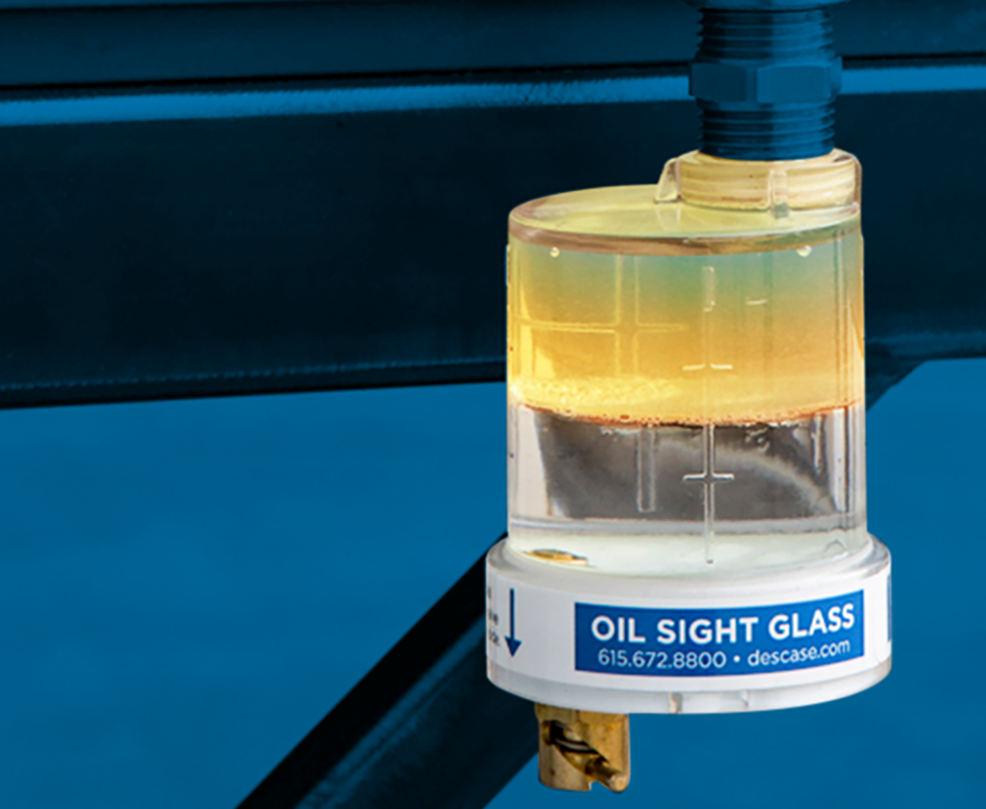
A simple way to detect the presence of water is to install a Bottom Sediment and Water Bowl (BS&W). This simple device should be installed in the pump drain, ideally below the lowest point of the oil pan. Since water is heavier than oil, it will naturally settle at the lowest point of the bearing housing. By installing the BS&W bowl at the lowest point, water can often be seen before it contaminates the oil that lubricates the bearings (Image 3).
The inclusion of a BS&W bowl has been added to the latest version of the American Petroleum Institute (API) 610 centrifugal pump standard used by the refining, petrochemical and natural gas industries.
3. oil color
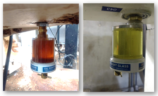
Each time the oil degrades, the color and clarity of the oil may change. Although a change in oil color is not always indicative of a serious problem, a sudden change, as shown in Image 5, should be reason enough for further oil analysis. BS&W Bowls and 3D Oil Glasses are two great ways to visually observe and record oil color.
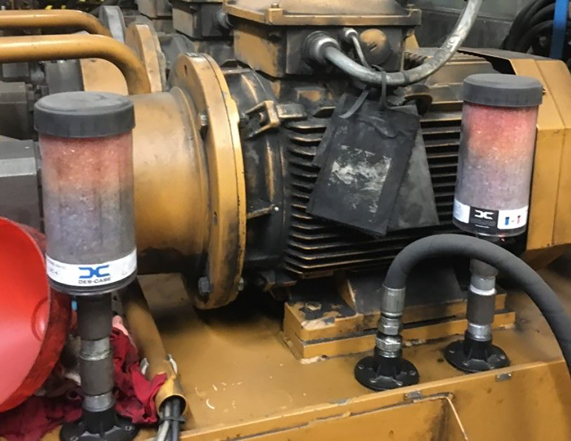
4. Desiccant Breather Inspections
In a previous Pumps & Systems article (“The Impact of Water on Pump Bearing Life”, August 2021), the author discussed the importance of controlling space humidity inside the bearing housing using a desiccant breather. However, a desiccant breather is more than just a means of preventing water from entering the pump. It can also serve as another visual inspection point. Due to the way air flows through a desiccant breather, the color indicator, which changes from blue to pink when saturated with moisture, will change color from bottom to top or top to bottom, depending on the circumstances. A color change from top to bottom indicates that water is present inside the bearing housing, possibly due to seal failure (image 6).
Like most rotating assets, pump life is closely tied to the health and cleanliness of the lubricant. By adding a few simple visual inspections to operators’ daily rounds, early warning signs of impending lubrication failures can be detected before a functional failure occurs.
Comments are closed.